

-
Products
-
-
-
-
Contact Us
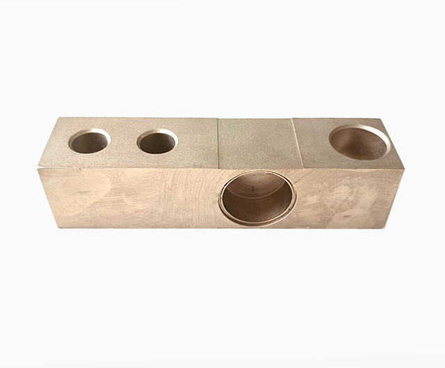
The knowledge you must master for CNC machining is all based on experience!
2026-01-27
Currently, most CNC lathes in China typically use standard three-phase asynchronous motors equipped with frequency converters to achieve stepless speed variation. Without mechanical reduction gears, the spindle often lacks sufficient torque at low speeds, and if the cutting load is too heavy, the machine can easily stall. However, some lathes are equipped with gear stages that effectively address this issue.
1. Influence on Cutting Temperature: Cutting Speed, Feed Rate, Cutting depth ;
Influence on cutting force: back-cut depth, feed rate, and cutting speed;
To Tool durability The effects of: cutting speed, feed rate, and depth of cut.
2. When the back cutting depth is doubled, the cutting force also doubles.
When the feed rate is doubled, the cutting force increases by approximately 70%.
When the cutting speed is doubled, the cutting force gradually decreases.
In other words, if you use G99, although the cutting speed increases, the cutting force won't change significantly.
3. The cutting force and cutting temperature can be determined by observing the discharge of iron chips to see whether they are within the normal range.
4. When the measured actual value X is greater than 0.8 times the diameter Y specified in the drawing for a concave circular arc, Auxiliary inclination angle The R produced by a 52-degree turning tool—specifically, the blade we commonly use with a 35-degree main rake angle and a 93-degree approach angle—may rub against the tool at the starting position.
5. The temperature indicated by the color of iron filings:
White below 200 degrees
Yellow: 220–240 degrees
Dark blue 290 degrees
Blue 320–350 degrees
Purple-black greater than 500 degrees
Red is greater than 800 degrees.
6. FUNAC OI mtc generally defaults to G commands:
G69: Cancel the G68 rotation coordinate system command
G21: Metric Dimension Input
G25: Spindle Speed Fluctuation Detection Disconnected
G80: Cancel fixed cycle
G54: Default Coordinate System
G18: ZX Plane Selection
G96 (G97): Constant Linear Velocity Control
G99: Feed per revolution
G40: Cancel tool tip compensation (G41 G42)
G22: Storage trip detection enabled
G67: Cancel macro program modal call
G64: This is an instruction for continuous-path programming in early Siemens systems, used to round off circles with axial tolerances. G64 was the original instruction that later evolved into G642 and CYCLE832.
G13.1: Polar Coordinate Interpolation Mode Cancelled
7. The external thread is generally 1.3P, while the internal thread is 1.08P.
8. Screw rotation speed S1200 / Pitch × Safety factor (typically 0.8).
9. Manual tool tip R compensation formulas: For chamfering from bottom to top: Z = R × (1 - tan(a/2)); X = R × (1 - tan(a/2)) × tan(a). To perform chamfering from top to bottom, simply change the subtraction sign to addition.
10. For every 0.05 increase in feed rate, the spindle speed should be reduced by 50 to 80 rpm. This is because reducing the spindle speed leads to slower tool wear and a more gradual increase in cutting forces, thereby compensating for the effects caused by the increased feed rate—namely, the rise in cutting forces and temperature.
11. Cutting speed and cutting force significantly affect the tool; excessive cutting force is the primary cause of tool breakage.
The relationship between cutting speed and cutting force: When the cutting speed increases while the feed rate remains constant, the cutting force gradually decreases. However, as the cutting speed increases further, tool wear accelerates, causing the cutting force to rise continuously. At the same time, the temperature also rises steadily. Once the cutting force and internal stresses become too great for the cutting blade to withstand, chipping or even blade failure will occur. (Of course, other factors, such as thermal expansion-induced stresses and a reduction in hardness due to temperature changes, also contribute to this phenomenon.)
12. During CNC turning operations, the following points should be given special attention:
(1) Currently, most economic CNC lathes in China typically use standard three-phase asynchronous motors equipped with frequency converters to achieve stepless speed variation. Without mechanical reduction gears, the spindle often lacks sufficient torque at low speeds, and if the cutting load is too heavy, the machine can easily stall. However, some lathes are equipped with gearshift options that effectively address this issue.
(2) As much as possible, ensure that the tool can complete the machining of an entire part or an entire work shift. For large parts undergoing precision machining, special attention should be paid to avoiding mid-process tool changes and ensuring that the tool can finish the machining in one go.
(3) When turning threads on a CNC lathe, try to use the highest possible cutting speed to achieve high-quality, efficient production.
(4) Use G96 whenever possible;
(5) The fundamental concept of high-speed machining is to ensure that the feed rate exceeds the heat-conduction rate, thereby allowing the cutting heat to be carried away with the chips and keeping the cutting heat isolated from the workpiece. This ensures that the workpiece either remains at a low temperature or experiences minimal temperature rise. Therefore, high-speed machining involves selecting a very high cutting speed paired with a high feed rate, while simultaneously opting for a relatively small depth of cut.
(6) Pay attention to the compensation for the tool tip radius R.
13. Vibrations and chipping frequently occur during turning operations:
The root cause of all this lies in the increased cutting forces and insufficient tool rigidity. The shorter the tool overhang, the smaller the back rake angle; the larger the blade area, the better the rigidity, and thus the greater the cutting forces the tool can handle. However, the wider the groove cutter, the greater the cutting force it can withstand—but its cutting force itself will also increase accordingly. Conversely, the narrower the groove cutter, the smaller the force it can handle, and consequently, its cutting force will also be lower.
14. Causes of vibration during turning:
(1) The excessive overhang of the cutting tool leads to reduced rigidity.
(2) A feed rate that is too slow can lead to an increase in specific cutting force, thereby causing significant vibrations. The formula is: P = F / Back Cutting Depth × f, where P represents the specific cutting force, F is the cutting force, and a spindle speed that is too high can also induce tool vibration.
(3) The machine tool lacks sufficient rigidity—meaning the cutting tool can handle the cutting forces, but the machine tool itself cannot. Simply put, the machine tool can’t perform the cutting operation. Generally, newly purchased machine tools won’t encounter this issue. Machine tools that do experience this problem are either very old or frequently subjected to “machine killers”—conditions that severely damage the machine tool.
15. When machining a part, at first the dimensions seemed fine. However, after working for several hours, we noticed that the dimensions had started to change and became unstable. The likely reason is that, at the beginning, since the cutting tools were brand-new, the cutting forces weren't very high. But after machining for some time, the tools wore down, increasing the cutting forces and causing the workpiece to shift slightly in the chuck. As a result, the dimensions kept drifting and became unstable.
16. When using G71, the values of P and Q must not exceed the sequence number of the entire program; otherwise, an alarm will occur: The format of G71-G73 instructions is incorrect—this is at least true in FUANC.
17. In the FANUC system, there are two formats for subprograms:
(1) The first three digits of P000 0000 indicate the number of cycles, while the last four digits represent the program number.
(2) The first four digits of P0000L000 represent the program number, and the three digits following the "L" indicate the number of loop iterations.
18. If the starting point of the arc remains unchanged and the endpoint is offset by a mm in the Z direction, then the position of the arc’s base diameter will be offset by a/2.
19. When drilling deep holes, the drill bit is not ground with cutting flutes to facilitate chip removal.
20. If you’re using a tool holder to drill holes, you can rotate the drill bit to change the diameter of the holes you’re drilling.
21. When drilling stainless steel center holes or stainless steel holes, the drill bit or... Center drill The center must be small; otherwise, it won’t be able to withstand the drilling force. When using a cobalt drill to make holes, avoid grinding grooves to prevent the drill bit from undergoing annealing during the drilling process.
22. According to the processing method, material cutting is generally divided into three types: cutting one piece at a time, cutting two pieces at a time, and cutting the entire bar stock at once.
23. When oval shapes appear during thread turning, it could be due to the material becoming loose. Simply use the threading tool to make a few more passes.
24. In some systems that support macro programming, macros can be used in place of subroutine loops, which not only saves program numbers but also avoids many potential complications.
25. If you’re using a drill bit to enlarge a hole but the hole’s runout is significant, you can switch to a flat-bottom drill for enlargement—but the twist drill must be short to enhance its rigidity.
26. When drilling holes directly with a drill bit on a drilling machine, the hole diameter may deviate. However, if you use a drilling machine to enlarge an existing hole, the enlarged hole diameter generally remains quite accurate—for example, if you use a 10 mm drill bit to enlarge a hole on a drilling machine, the resulting hole diameter will typically be within a tolerance of about 3 microns.
27. When drilling small holes (through-holes), try to ensure that the chips are continuously and smoothly curled and then discharged from the tail end. Key points for chip curling: First, position the tool appropriately higher; second, adjust the feed rate appropriately. Rake angle Pay attention to the depth of cut and feed rate—never set the cutting tool too low, as this can easily cause chips to break off. If the secondary relief angle of the tool is large, even if chips do break off, they won't get stuck in the tool holder. However, if the secondary relief angle is too small, the chips, once broken off, may become lodged in the tool holder, posing a potential hazard.
28. The larger the cross-sectional area of the tool holder in the hole, the less likely it is to experience chatter. Additionally, you can tie a strong rubber band around the tool holder, as a strong rubber band can help absorb vibrations to some extent.
29. When turning copper holes, the radius R at the cutting edge of the tool can be slightly larger (R0.4–R0.8), especially when turning tapers. While this may not pose much of a problem with iron parts, copper parts tend to get severely clogged with chips.
More news

Hotline
Technical Support
Address
No. 1, Building 1, Yin Cang Road, Green Industry Cluster, Quzhou City, Zhejiang Province
Follow us



Copyright © 2024 Zhejiang Nan Hua Electronic Technology Co., Ltd. | Powered by www.300.cn