

-
Products
-
-
-
-
Contact Us
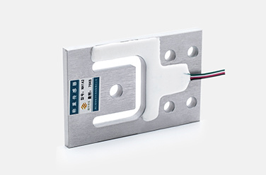
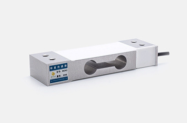
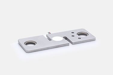
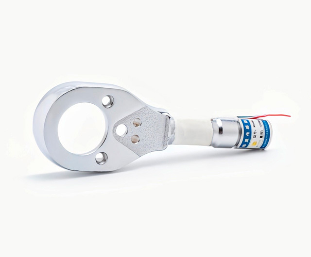
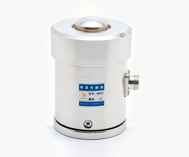
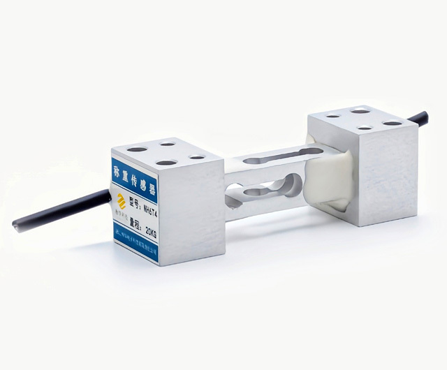
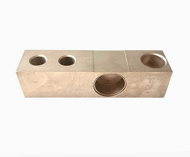
Properly install and calibrate the weighing sensor
2025-10-30
Imagine your device is like a four-legged table—but each leg is supporting a different weight. If it’s not installed properly in this scenario, the weighing results will be severely distorted: at best, this affects data accuracy; at worst, it could lead to equipment damage or even safety hazards.
Don’t worry—by understanding the principle and following the right steps, you can ensure that each sensor "performs its own function," accurately reflecting the true weight. The key lies in: independent load distribution at four points, precise leveling, and eliminating angular discrepancies.
1. Why can't we just "install it and be done"? We must adjust each corner individually!
The equipment has different weights at its four corners, meaning each sensor experiences a significantly varying initial load (which we call "tare weight"). If you simply mount the sensors without making any adjustments, what problems might arise?
Reading distortion: Lighter corners may not yet reach the lower limit of the sensor's effective measurement range, while heavier corners could already be approaching the upper limit—or even exceeding it—leading to significantly low or high overall readings, and introducing nonlinearity into the process.
Sensor Overload Risk: The heaviest load may remain under high stress for extended periods, shortening the sensor's lifespan or even causing damage.
Structural Stress: The equipment base or weighing platform may experience twisting and deformation due to uneven stress, compromising long-term stability.
Therefore, the core principle of installation is to ensure that each sensor operates within its linear and safe working range, while using the instrument’s “angle difference compensation” function to eliminate errors caused by uneven weight distribution.
2. How to Properly Install the Sensor Body? Ensure the "Foundation" Is Firm and Stable.
Ensure the sensor body is correctly installed to guarantee a stable "foundation." The key is to follow the three-step principle: "first adapt to the environment → then precisely secure the sensor → finally verify its stability." This approach provides full-process control—from initial preparation to thorough post-installation checks—helping to prevent data inaccuracies or equipment damage caused by loose installations. Below are the specific operational steps and critical points to keep in mind.
1. Before Installation: Complete 3 Core Preparations to Avoid Misalignment
Preparation before installation directly determines the subsequent stability, so it’s crucial to carefully verify the compatibility of the installation environment, tools, and the sensor itself.
Confirm the installation environment and mounting surface conditions
Check the flatness of the mounting surface: Use a level or straightedge to measure, ensuring that the plane error of the mounting surface (such as walls or equipment surfaces) is ≤0.5 mm/m. This prevents uneven stress on the sensor caused by surface irregularities, which could lead to loosening over time with prolonged use.
Clean the mounting surface of any impurities: Wipe the mounting surface with alcohol or a dry cloth to remove dust, oil stains, and rust. If the surface is concrete or metal, lightly sand it beforehand to ensure smoothness, preventing impurities from compromising the secure attachment (e.g., screws slipping or adhesive failing to stick firmly).
Match environmental characteristics: If the sensor is used in damp, high-temperature, or vibration-prone environments, ensure proper protection of the mounting surface beforehand (e.g., by applying waterproof adhesive pads, installing thermal insulation brackets, or securing a shock-absorbing base). This will prevent environmental factors from indirectly compromising the stability of the installation.
Verify sensor installation parameters and accessories
Check the product manual: Confirm the sensor installation method (e.g., screw fixing, adhesive mounting, or snap-fit), recommended installation torque (e.g., ensure screw torque is controlled between 2–3 N·m to avoid damaging the unit by tightening too much, or causing looseness if too loose), and installation direction (e.g., the gravity sensor must be installed vertically; tilting can affect data accuracy and may lead to structural stress).
Prepare the appropriate mounting accessories: Select the matching accessories based on the installation method. For example, if using screw fixation, choose screws that match the material of the mounting surface—use self-tapping screws for metal surfaces and expansion screws for concrete surfaces. For adhesive mounting, use industrial-grade sensor-specific glue (avoiding ordinary double-sided tape, as its insufficient adhesion may lead to detachment). Additionally, ensure that the accessory specifications perfectly align with the sensor’s mounting hole dimensions; for instance, an M4 screw should correspond exactly to a 4mm mounting hole, with a clearance no greater than 0.1mm.
Planning the installation location and force application angle
Avoid areas of concentrated stress or vibration sources: The sensor should be installed away from components experiencing intense vibrations (such as near motors). If avoidance is not possible, install an elastic shock-absorbing bracket to minimize the impact of vibrations on the mounting structure. Additionally, ensure the sensor body itself is not subjected to additional external forces (e.g., cable pulling or pressure from other equipment), and leave at least 5 cm of surrounding clearance.
Ensure the installation angle meets the requirements: For example, the displacement sensor must be parallel to the measurement direction, with an angular deviation of ≤1°; the pressure sensor must have its pressure interface oriented vertically—upward or downward (as specified in the manual)—to prevent uneven stress on internal components caused by angular misalignment, which could indirectly compromise the stability of the mounting base.
II. Installation: Follow the 4-step procedure carefully to ensure secure fastening.
The installation process must strictly follow the operational procedures, with a focus on controlling the tightening force, ensuring proper sealing and protection, and handling cables carefully—avoiding any potential looseness caused by improper handling.
Positioning marker: Accurately determine the installation location
Use a pencil or marker to mark the center points of the sensor mounting holes on the mounting surface. If there are multiple mounting holes (such as four holes arranged in a rectangle), use a measuring tape to accurately measure the distances between the holes, ensuring perfect alignment with the sensor’s mounting holes (tolerance ≤0.2mm). This will prevent forcing the installation, which could lead to sensor deformation or screws that cannot be fully tightened.
If installing by adhesion, mark the sensor's outline on the mounting surface to ensure precise centering during application, and make sure the adhesive area covers more than 90% of the sensor's bottom (to prevent localized lifting, which could cause edges to curl over time with prolonged use).
Fixed operation: Perform according to installation guidelines.
- Screw fastening (most commonly used, offering the highest stability)
First, use a drill bit to create pilot holes at the marked points, with the hole diameter 0.5–1 mm smaller than the screw diameter (e.g., drill a 3.2 mm hole for an M4 screw). Ensure the drilling depth is 2–3 mm deeper than the screw length (to prevent the screw from bottoming out and becoming impossible to fully tighten).
Align the sensor with the mounting hole, insert the screw, and then tighten it using a torque wrench according to the torque specified in the instruction manual. (Do not tighten by hand until the end and then tap it with a hammer, nor apply excessive force with an adjustable wrench, to prevent the screw from stripping or the sensor housing from cracking.)
If there are multiple screws, tighten them in stages following a "diagonal sequence" (e.g., for 4 screws, proceed in the order of "top-left → bottom-right → top-right → bottom-left"), applying 50% of the specified torque each time, and then repeat until reaching the standard torque. This ensures even stress distribution across the sensor, preventing warping.
- Paste and secure (suitable for lightweight sensors with a flat mounting surface)
Apply industrial adhesive evenly to the bottom of the sensor or the mounting surface, ensuring the adhesive layer is between 0.1 and 0.2 mm thick (too thick may cause bubbles, while too thin could result in insufficient adhesion). Avoid applying the adhesive around the sensor's interface and heat dissipation holes.
Attach the sensor firmly to the mounting surface at the marked position, applying even pressure—approximately 5–10 N—using your hand or a fixture. Hold it in place for 30–60 seconds to ensure the adhesive layer adheres completely. Then, allow the assembly to sit undisturbed according to the adhesive’s curing time; for instance, epoxy adhesives typically require 24 hours of rest before fully curing, during which time the sensor must remain untouched.
- Snap-fit fastening (suitable for scenarios requiring frequent disassembly)
First, install the clip base onto the mounting surface using the screw-fixing method, ensuring the base is securely fastened without any looseness (apply torque according to the base’s specifications).
Align the sensor with the base clip, press vertically downward until you hear a "click," then gently pull the sensor to ensure it’s securely in place. If the clip has a locking screw, make sure to tighten it further (to prevent vibrations from causing the clip to come loose).
Sealing and Protection: Enhancing Environmental Adaptability, Indirectly Strengthening the Foundation
If the installation environment is humid or dusty, apply sealant (such as silicone) into the gaps between the sensor and the mounting surface. The sealant should be approximately 5–8 mm wide and 1–2 mm thick, completely covering all gaps to prevent moisture or dust from entering the mounting holes, which could cause screws to rust or adhesive tape to lose its effectiveness.
If the sensor has a cable interface, the cable must be securely fastened along the mounting surface (using cable clips or zip ties), ensuring that the cable's bending radius is at least 5 times its diameter. This prevents the cable's own weight or tensile forces from being transmitted to the sensor body, which could otherwise cause the mounting point to loosen.
Cable handling: Avoid transmitting external forces to the main body
The sensor cable should be预留 with an extra 10–15 cm of length (to prevent the cable from tightening due to equipment vibration). The excess portion must be neatly coiled into a loop and securely固定 to the mounting surface—positioned away from the sensor body—to avoid any potential collision with the sensor if the cable sags or swings.
If the cable needs to pass through metal or concrete holes, a rubber grommet must be installed inside the hole to prevent the cable jacket from being scratched by sharp edges, while also avoiding long-term wear caused by friction between the cable and the hole wall—thereby indirectly protecting the sensor mounting structure.
III. After Installation: 2 Key Checks to Verify Stability
After installation is complete, a physical inspection and trial run are required to ensure that the "foundation" is free of any hidden issues, preventing loosening during later use.
Physical Stability Check
Manual Inspection: Gently shake the sensor body by hand (applying a lateral force of 1–2 N), and ensure there is no noticeable displacement or loose, abnormal noise. Use a wrench to check the screws (if the sensor is secured with screws), confirming that none are stripped or experiencing torque degradation. (Re-tighten to the standard torque setting—if no significant rotation occurs, the inspection is合格.)
Tool inspection: Use a level to reconfirm that the sensor installation angle meets the requirements. Randomly check the screw torque using a torque wrench (sampling rate ≥50%) to ensure all fastening points meet the specified torque standards. If the sensor was installed by adhesive bonding, after 24 hours of curing, gently pull on the sensor with a tensile tester (pull force ≤ twice the sensor's weight). If the sensor remains securely in place without detaching, it passes inspection.
Trial Operation Verification
Power-on trial run: Apply power to the sensor and operate it continuously for 24 hours, monitoring during this period to ensure stable sensor data (with no jumps or deviations caused by vibration). At the same time, re-inspect the mounting points to confirm that no loosening has occurred due to temperature changes or vibrations—such as slight screw loosening or edges lifting at adhesive areas.
Simulation Condition Testing: If the sensor is intended for use under specific conditions (such as the vibration environment during equipment operation), the equipment must be started to simulate normal operating conditions. After running for 1–2 hours, shut down the equipment and perform an inspection to ensure that the sensor mounting structure remains free from deformation and that all fixing points are securely in place. Finally, verify that data acquisition is functioning properly.
Got it! By following these core steps—“secure installation and precise corner adjustment”—your weighing system will achieve high accuracy and reliability, even if the equipment has significantly uneven weight distribution across its four corners. Remember: a stable, level foundation, proper mechanical installation, and accurate corner-difference calibration are all essential—and none can be overlooked.
Always carefully perform angle difference compensation after each installation—this is the "golden key" to resolving issues caused by uneven angular loading. With meticulous attention to detail, you can ensure that every sensor accurately "reports" the weight it’s bearing, allowing the entire system to deliver reliable data—and keep everything running smoothly for you! 

Next page
More news

Hotline
Technical Support
Address
No. 1, Building 1, Yin Cang Road, Green Industry Cluster, Quzhou City, Zhejiang Province
Follow us



Copyright © 2024 Zhejiang Nan Hua Electronic Technology Co., Ltd. | Powered by www.300.cn