

-
Products
-
-
-
-
Contact Us
Weighing Sensor Quality Check: A 4-Step Guide to Accurate Diagnosis
2026-11-17
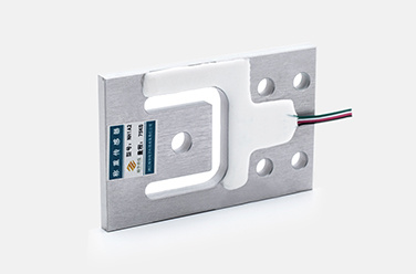
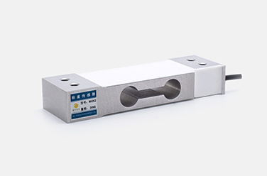
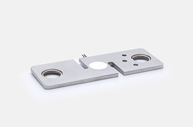
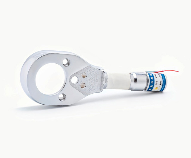
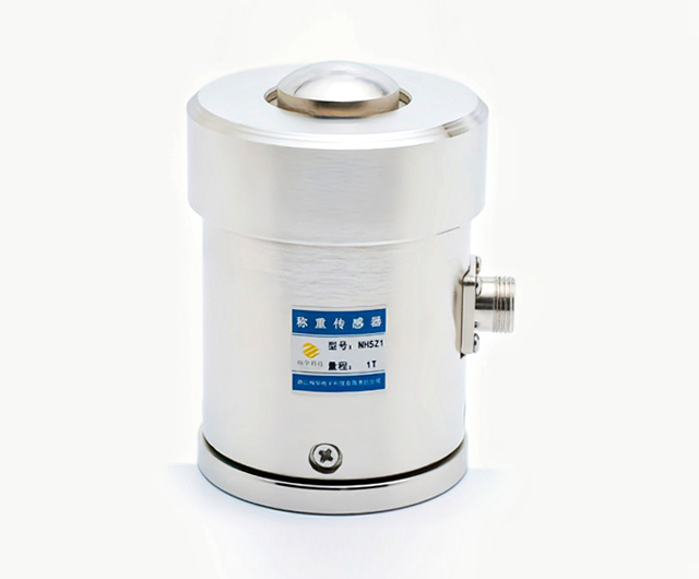
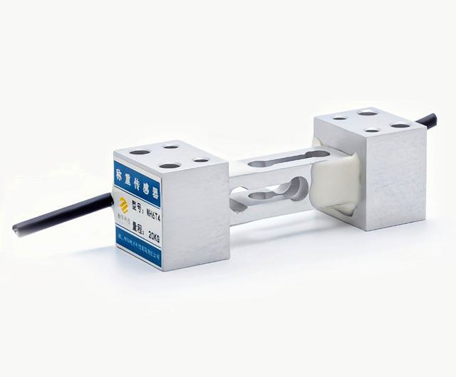
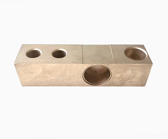
Weighing sensors are the core sensing elements of electronic weighing instruments, and their performance parameters directly determine the system’s measurement accuracy. When faced with issues such as inaccurate weighing or data drift, many users are unable to quickly identify faults in the sensor itself. This article outlines four practical testing procedures to guide users in performing basic health assessments of weighing sensors without specialized calibration equipment.
I. Visual and structural inspection to identify obvious faults
First, a preliminary screening is conducted through visual inspection and physical verification:
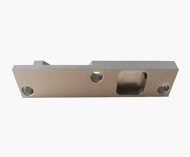
- Body appearance: Inspect the elastomer for dents, deformation, or cracks, and check the lead cables for damage, aging, or loose terminals; any of these defects can directly cause abnormal signal transmission.
- Sealing performance: Load cells typically feature a sealed protective structure; if the seal comes loose or water enters the cavity, it can easily cause a short circuit in the internal bridge circuit. Use a multimeter set to continuity mode to check for conductivity between the signal wires and the housing; under normal conditions, there should be no continuity.
- Installation conditions: For installed sensors, verify that the load application points have not shifted and that the fastening bolts are securely tightened. Sensor tilt or eccentric loading can cause irreversible plastic deformation of the elastomer, resulting in permanent loss of measurement accuracy.
II. Static Resistance Measurement: Using a Multimeter for Rapid Bridge Circuit Status Screening
This method is the most commonly used on-site technique for basic testing; it is recommended to use a high-precision digital multimeter:
- Input resistance: Measure between the excitation terminals EXC+ and EXC-. The typical range is 380 Ω to 420 Ω (refer to the product manual). A reading of 0 Ω indicates a bridge short circuit, while an infinite reading indicates an open circuit in the excitation loop.
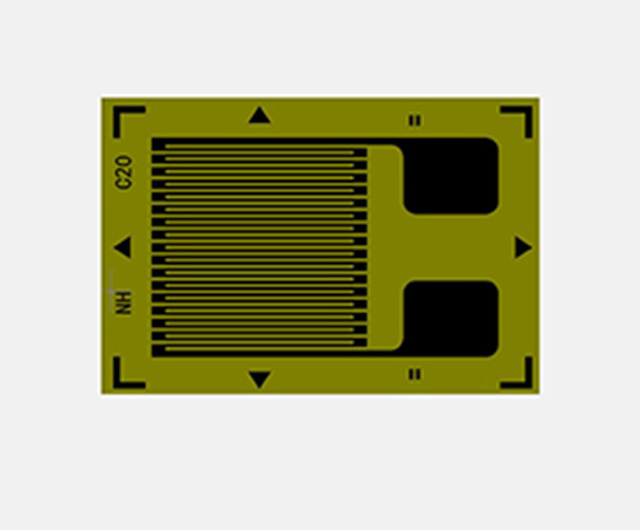
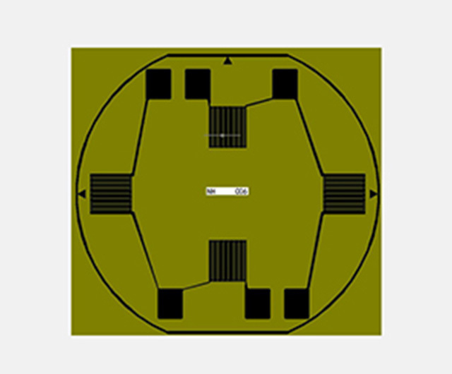
- Output resistance: Measure at the signal terminals SIG+ and SIG-. The normal output resistance is typically 5–10 Ω lower than the input resistance. If the measured value deviates significantly from the standard range, it most likely indicates damage to an internal strain gauge.
- Insulation Resistance: Use the megohmmeter setting to measure the insulation resistance between the signal wire and the sensor housing; the acceptable value should be greater than 500 MΩ. If the insulation resistance is too low, it indicates a potential leakage hazard, and the sensor must not be put back into service.
-

III. Load Test to Verify Dynamic Metering Performance
After passing the static resistance test, the sensor’s dynamic characteristics must be verified through a load test:
- Zero-point stability: After power-up, observe the instrument’s zero-point output. If the zero point continues to drift beyond ±0.1%FS, it indicates that the zero-point temperature drift exceeds the limit or that line interference is present.
- Linearity test: Standard weights are used to apply incremental loads, and data are collected at multiple points corresponding to 20%, 40%, 60%, 80%, and 100% of the rated range. The indicated value error is compared; under normal operating conditions, the error should be ≤0.3% FS. If the error exhibits abrupt changes within a specific range, it usually indicates failure of the strain gauge.
- Hysteresis error test: After loading to full scale, unload in steps and compare the difference between the indicated values during loading and unloading at the same load; a difference greater than 0.2% FS indicates that the elastomer’s hysteresis characteristics exceed the specification.
-

IV. Environmental Interference Troubleshooting to Avoid Misdiagnosis of Faults
Some weighing anomalies are not due to sensor failure but to external operating conditions; prioritize troubleshooting the following:
- Electromagnetic interference: High-power sources in the vicinity, such as variable-frequency drives and welding equipment, can interfere with weak sensor signals. The interference source can be shut down and the measurement repeated; if the data stabilizes, additional shielding and grounding measures should be implemented.
- Temperature effects: The sensor is sensitive to temperature changes; operating outside its rated range (typically −10°C to 60°C) can cause zero-point drift. Recalibration and verification under ambient conditions are recommended.
- Cable attenuation: If the signal cable is too long (>10 m), signal attenuation may occur. Shorten the cable or use a matching signal amplifier to observe output stability.
Through these four inspection steps, the type of load cell failure can be quickly identified. If the sensor itself is found to be damaged, prioritize replacing it with a unit of the same model and accuracy class. During installation, ensure proper alignment and even force distribution, and strictly control overload conditions to maintain measurement stability and extend the sensor’s service life.

Previous page
Next page

Hotline
Technical Support
Address
No. 1, Building 1, Yin Cang Road, Green Industry Cluster, Quzhou City, Zhejiang Province
Follow us



Copyright © 2024 Zhejiang Nan Hua Electronic Technology Co., Ltd. | Powered by www.300.cn