

-
Products
-
-
-
-
Contact Us
Key Points of Conventional Strain Gauge Mounting Techniques
2026-03-23
It is well known that a complete vehicle, during actual operation, is subjected to a wide variety of internal and external loads. Design engineers must understand the magnitude and distribution of these loads in order to develop a sound design—one that avoids both overdesign, which can result in vehicle structures that are excessively robust yet fail to perform optimally over their intended service life, and underdesign, which can lead to premature failure of critical structural components. Consequently, before finalizing the vehicle’s design, extensive load-testing is required, involving numerous structural components; and at the heart of such testing lies the most fundamental measurement element: the strain gauge.

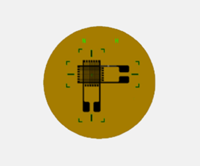
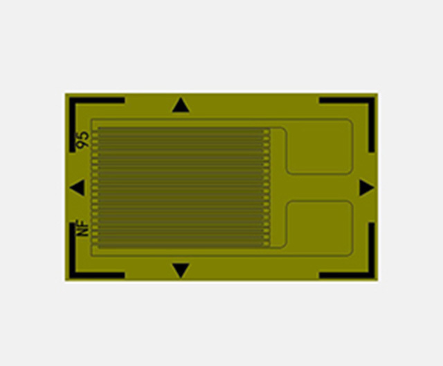
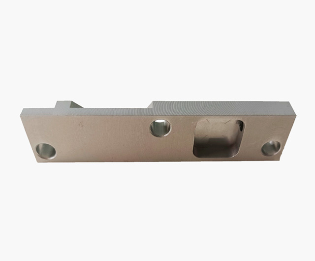
Strain gauges can measure strain, stress, force, bending moment, torque, displacement, and other parameters of the entire vehicle structure. For such measurements, the strain gauge is simply bonded to the surface of the test specimen and connected to a data acquisition system. Another common application involves bonding strain gauges to elastic elements and then connecting them to signal-conditioning circuits to form various types of force sensors. The force sensors used for routine vehicle-load measurement, as well as many scales encountered in everyday life, all incorporate strain-gauge-based sensing circuits internally.
So, what are the typical steps or precautions involved in the installation and use of strain gauges?
Strain gauges can measure strain, stress, force, bending moment, torque, displacement, and other parameters of the entire vehicle structure. For such measurements, the strain gauge is simply bonded to the surface of the test specimen and connected to a data acquisition system. Another common application involves bonding strain gauges to elastic elements and then connecting them to signal-conditioning circuits to form various types of force sensors. The force sensors used for routine vehicle-load measurement, as well as many scales encountered in everyday life, all incorporate strain-sensing circuits internally.
So, what are the typical steps or precautions involved in the installation and use of strain gauges?
Confirm test requirements:
All the strain-testing work we undertake originates from test requirements submitted by the design department, which specify whether the objective is to measure structural stresses or to quantify specific applied loads. Furthermore, the testing objectives—whether to characterize actual load levels or to conduct life-cycle assessments—also influence the selection of appropriate measurement strategies. The choice of strain-gauge configuration is therefore closely aligned with the specific goals of the experimental study.
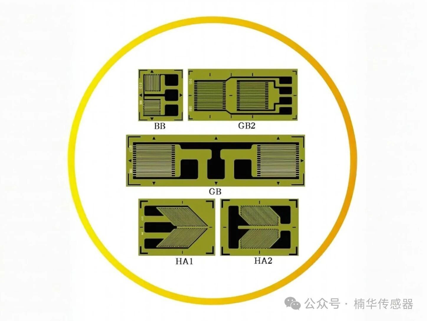
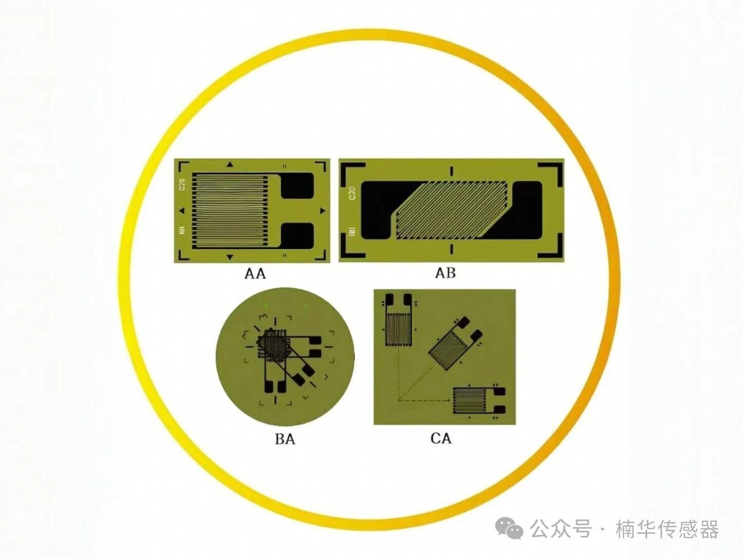
Strain gauge selection:
There are many types of strain gauges available on the market, and extensive online resources are readily accessible to help you understand the subtle differences. If you’d rather not spend time sifting through numerous documents online to identify these distinctions, consider reaching out to strain-gauge sales representatives. Simply outline your specific requirements, and they will be able to recommend the most suitable gauge—especially for applications with specialized needs.
Inspection of the test item or the vehicle under test:
On occasion, the design department will suddenly request a load-test requirement, only to find that the test article either does not exist or that the existing article is no longer suitable for testing. In such cases, it is essential to thoroughly discuss whether the measurement is truly necessary. Additionally, during the later stages of testing and measurement, changes to certain parameters or other modifications may cause slight variations in vehicle behavior. In these situations, we must verify which parameters or structural elements have been altered, what impacts these changes will have, and whether they will affect our load measurements—essentially confirming that our tests are being conducted under the correct conditions and yielding results that reflect the environment envisioned by the designers.
Routine strain gauge testing:
In fact, we complete this task simply by preparing the strain gauges in advance: we visually inspect each gauge for physical damage, check the sensing grid for rust spots, examine the two leads associated with each gauge for signs of breakage, and look for bubbles, wrinkles, or pitting on the backing film. We also measure the resistance to ensure it is within specifications. However, such inspections are primarily conducted to address quality concerns that may arise from frequent handling—such as repeated repackaging and relocation—of the strain gauges. Under normal circumstances, strain gauges are stored in their original shipping packaging, where they generally remain in good condition; in these cases, a thorough inspection can often be omitted.
Sample surface treatment:
Strain gauges should not be applied directly to the surface of the test specimen, as this would result in adhesion to paint or rust, leading to poor bonding and inaccurate measurement results. Prior to application, the area to be bonded should be lightly ground down to expose a small, clean surface; for single-strain-gauge applications, an area roughly the size of a thumbnail is sufficient. Rust on the structural surface of steel test specimens can be removed using a handheld electric grinding wheel, followed by sanding with 220–400 grit sandpaper selected according to the material of the specimen. The reason for sanding is that if the steel surface is too rough, the strain gauge will be difficult to adhere properly, whereas if it is too smooth, the gauge may slip. Typically, the sanding direction is set at a 45-degree angle relative to the gauge-attachment direction, which is expected to facilitate secure bonding under these conditions.
Underline positioning:
To ensure the accurate placement of the strain gauge, a compass-like tool can be used to lightly scribe crosshairs at the bonding location. When drawing the lines, apply gentle pressure as the lines pass over the gauge attachment point to avoid excessive scoring and potential damage to the bonded strain gauge.
Patch:
After surface scribing is completed, wipe the surface with a cotton swab soaked in acetone or anhydrous ethanol, ensuring that the wiping motion is in a single direction until no black residue remains on the swab. At the same time, maintain a clean cleaning environment on site to prevent external dust from entering the cleaning area.
Apply a thin layer of adhesive to the surface where the strain gauge is to be mounted, then affix the gauge to the desired location. Simultaneously cover the gauge with a polyvinyl chloride film and repeatedly press down on the film with your fingers, aiming to push the adhesive from one end of the gauge to the other and then out through the edges. Continue applying firm pressure for a short period, and remove the film only after the adhesive has substantially cured.
If this procedure is performed in the dead of winter, it is best to preheat the area with a heat gun beforehand, as this will facilitate the application of the strain gauge in cold ambient conditions.
Patch quality inspection:
After the component placement is completed, first visually inspect whether the components are placed at the positions we specified. Even a slight deviation is unacceptable.
It’s acceptable—as long as we ourselves are satisfied with it, we can basically pass.
After the strain gauge has been bonded, it should be inspected. First, verify that the gauge leads are electrically insulated from the structure being tested; this can be done using a multimeter. Next, measure the resistance value to confirm the reading. Finally, visually assess the bonding quality and check for any bubble-like defects within the gauge.
Welding wire:
In this step, soldering is performed using a soldering iron and solder wire, with the requirement that all solder joints be clean, smooth, and free of cold or false joints. A terminal block must be used to connect the lead wires to the strain gauge leads, ensuring that the terminal block is pressed firmly against the strain gauge to prevent short circuits caused by direct contact between the leads and the specimen surface. Whenever possible, before soldering the strain gauge leads to the terminal block, slightly bend the leads outward at the end of the lead wire prior to soldering; this creates a small slack in the lead, which can be advantageous in case of emergencies later on.
The welding time must be kept short; the weld should be completed quickly in a single, continuous pass to prevent thermal damage to the strain gauge leads caused by excessive heat.
At this point, quickly repeat the previous insulation and resistance checks using a multimeter.
Sealed Protection:
If the ambient climate is relatively humid, or if the test specimen needs to be stored for an extended period before repeated testing, or if the testing duration is prolonged, moisture-proof measures must be implemented for the strain gauges to ensure their proper operation. These measures should cover both the strain gauge itself and its lead wires as well as the wiring terminals; a small soft brush can be used to apply a thin coat of women’s nail polish to these areas.
Wire Number:
After sealing and protecting the leads, use a multimeter to measure the resistance of each strain gauge at the opposite end of the lead. Then, label the lead end with tape or small cable ties, indicating the corresponding channel number and name, to facilitate subsequent configuration of the data acquisition software.
Connection to data acquisition and software configuration:
Connect all channels to their corresponding ports on the data acquisition system, enter the channel information in the software while matching it with the wire labels, and then perform zeroing calibration of the strain gauges. However, a crucial step is to ensure that the vehicle’s loading condition at the time of zeroing is accurately documented—specifically, the environmental conditions under which zeroing is performed. After zeroing, conduct a preliminary data acquisition to verify that the strain or stress signals are correct; at this stage, gently press the gauge with a cotton swab, which should produce a change of approximately 20 microstrains. Once the pressure is released, the signal should return to zero. Then proceed with a brief formal data acquisition, followed by a return to the original zeroing environment to confirm that the signal has indeed returned to zero.
In summary, the preceding section has outlined the basic steps and key considerations for strain gauge installation in typical applications. For certain specialized high-temperature environments, if you lack confidence in performing the installation yourself, it is advisable to collaborate with the supplier. Proper strain gauge installation is critical to ensuring high-quality signal acquisition in the subsequent stages—only then can we obtain accurate signals that precisely meet the design requirements.
More news

Hotline
Technical Support
Address
No. 1, Building 1, Yin Cang Road, Green Industry Cluster, Quzhou City, Zhejiang Province
Follow us



Copyright © 2024 Zhejiang Nan Hua Electronic Technology Co., Ltd. | Powered by www.300.cn