

-
Products
-
-
-
-
Contact Us


Solution for eliminating the need for zero-point adjustment in a multi-sensor weighing system using load cells
2025-04-24
In industrial applications, angular error is a significant source of error in multi-sensor weighing systems, affecting the accuracy and stability of weighing. Angular error refers to the difference in readings displayed by different weighing sensors under the same weight. This difference can be caused by various factors, including manufacturing errors of weighing sensors, inaccurate installation, and signal interference. Load cells composed of analog weighing sensors, due to the indistinguishability of signals, require adding weights to each weighing sensor during calibration and adjusting the angular error using potentiometers in the junction box. However, there is interaction between the weighing sensors, requiring repeated adjustments, significantly increasing enterprise costs [1]. Therefore, designing a multi-sensor weighing system that eliminates the need for angular error adjustment has significant advantages in practical applications, helping to improve the accuracy and efficiency of industrial processes while reducing operating costs.
1. Angular Error Adjustment of Multi-Sensor Weighing Systems
A multi-sensor weighing system converts the weight of an object on a load cell into a proportional analog signal under the action of gravity via analog weighing sensors. This signal is then aggregated and connected to a junction box. An analog weighing instrument collects the output from the junction box, processes the data, and converts it into directly displayed weight data. The block diagram of a multi-sensor weighing system is shown in Figure 1. The system can be divided into three parts: an analog weighing display instrument, a junction box, and a load cell (analog weighing sensor, force transmission and limit mechanism, load platform). Typically, angular error testing requires adding a certain amount of weight to the load cell for initial calibration [2]. After calibration, the weight is removed, and a four-corner error test is performed. Appropriate weights are placed at positions "①", "②", "③", and "④" shown in Figure 1, i.e., each corner of the load cell, to check the error between the instrument display value and the actual value. If there is an error, the potentiometer corresponding to the analog weighing sensor with an offset exceeding the tolerance needs to be adjusted to correct the angular error. Due to the interaction between analog weighing sensors, repeated adjustments are needed to meet the requirements. This adjustment process is very cumbersome and time-consuming.

2. Design of a New Bridge Circuit to Eliminate Angular Error Adjustment
Through in-depth analysis of the factors causing angular error, this paper develops a new bridge circuit board that can achieve high-precision measurement in multi-sensor weighing systems without relying on subsequent cumbersome and time-consuming angular error adjustments, directly providing a solution that eliminates the need for angular error adjustment.
The circuit diagram of the new bridge circuit board is shown in Figure 2. The bridge circuit board uses all surface mount resistors. Its innovation lies in the arrangement of three Z resistor configuration points at the output end, labeled Z1, Z2, and Z3. The purpose of this circuit design is to obtain the "highest symmetry" of the Z resistors on both sides of the bridge circuit, that is, to make the combined value of Z1 and Z3 as close as possible to the value of Z2, thereby ensuring that the angular error of the entire weighing sensor system is minimized.
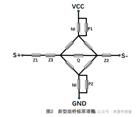
This paper uses the term "highest symmetry" instead of "absolute symmetry" because electronic component manufacturers, to simplify the specification management of resistor values, follow a standardized resistor value series, namely the EIA standard. Common series include E6, E12, E24, E48, E96, E192, etc. These series provide standardized options for the production and selection of resistor values. In actual production, enterprises need to balance material management costs and system accuracy requirements. For low-accuracy weighing sensor systems, E48 series resistors are usually sufficient to eliminate angular error adjustment. However, for systems requiring higher accuracy, more precise E96 series resistors may be needed to ensure that the system meets the required high-performance standards. In this way, the maximum symmetry of the Z resistors can be achieved, thus truly realizing angular error-free adjustment for high-accuracy weighing sensor systems.
3. Verification of Angular Error-Free Adjustment in Multi-Sensor Weighing Systems
To verify the advantages of the new bridge circuit board in terms of angular error performance, a series of detailed and rigorous tests, including comparative tests, must be performed to comprehensively assess the angular error performance. This paper presents two verification test methods: simulated weighing system testing on a testing machine and platform weighing system testing. Through these two comprehensive performance evaluation tests, the new bridge circuit board can be more accurately judged to determine whether it truly achieves angular error-free adjustment.
3.1 Verification of Angular Error-Free Performance in Simulated Weighing System on a Testing Machine
In multi-sensor weighing systems, angular error is affected not only by electrical signals but also by the stiffness of the load cell, the latter being particularly crucial for test repeatability. To more accurately reflect the influence of electrical signals, especially the specific influence of Z resistor asymmetry on angular error, simulated weighing system testing on a testing machine provides a more intuitive assessment method. This test used eight analog weighing sensors (numbered 1#, 2#…8#) and randomly assembled them into six weighing systems based on four weighing sensors. Three different Z resistor asymmetry conditions were specifically designed: Condition 1: asymmetry value less than 1Ω; Condition 2: asymmetry value less than 3Ω; Condition 3: asymmetry value less than 7Ω. This design aims to analyze in depth the specific impact of Z resistor asymmetry on the angular error of the simulated weighing system on the testing machine. The test results are systematically recorded in the table below.

By analyzing the test data in the table above, it can be clearly seen that the higher the asymmetry of the resistors on both sides of the bridge circuit of the bridge circuit board of a single weighing sensor, the more significant the corresponding angular error on the testing machine. The experimental results show that, while maintaining the consistency of the sensitivity of the weighing sensors, ensuring that the asymmetry difference of the Z resistors on both sides of the bridge circuit of the bridge circuit board of each weighing sensor does not exceed 1Ω can achieve angular error-free adjustment for high-accuracy weighing systems.
3.2 Verification of Angular Error-Free Performance in Multi-Sensor Platform Weighing System
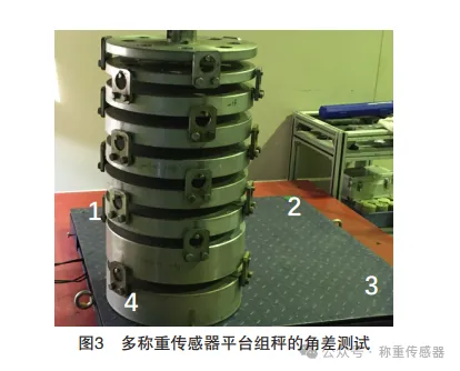
Angular error testing of multi-sensor platform weighing systems is crucial for ensuring the accuracy and stability of the weighing system. To verify the specific impact of Z resistor asymmetry on the angular error of multi-sensor platform weighing systems, a total of 16 analog weighing sensors using the new bridge circuit board were produced, and 12 1.5T platform scales with an accuracy of C3 were randomly assembled for comparative testing. The weighing sensors were numbered 1#, 2#…16#. According to product standards, the allowable angular error of this weighing system should be controlled within 0.5kg. The platform weighing system test is shown in Figure 3. Weights are loaded sequentially at the four positions shown in the figure, and the measured weight at each position is recorded sequentially to calculate the angular error.
In the platform group scale corner difference verification test, two cases of Z resistor asymmetry affecting the corner difference were explored. The first case investigated the impact of a larger Z resistor asymmetry value, i.e., Z2-Z1 > 3Ω, on 12 scales through corner difference testing. The second case adjusted the Z resistor asymmetry value to keep it within a smaller range, i.e., Z2-Z1 < 1Ω, and similarly conducted corner difference tests on 12 scales. The test results of the corner difference performance of the platform group scale simulated using the new group bridge board are clearly shown in Figure 4, intuitively reflecting the impact of Z resistor asymmetry changes on the platform group scale corner difference.

The green line in Figure 4 represents the 0.5kg corner difference acceptance standard line. According to the data in Figure 4, when the Z resistor asymmetry value of the weighing sensor group bridge board exceeds 3Ω, the corner difference of all 12 scales participating in the test exceeded the acceptance standard, as shown by the orange line in Figure 4. Conversely, when the Z resistor asymmetry value of the weighing sensor was adjusted to below 1Ω, the corner difference of all scales met the accuracy requirements, as shown by the blue line in Figure 4. The experimental results clearly indicate that when the asymmetry of the Z resistors at both ends of the group bridge circuit is controlled within 1Ω, high-precision group scale systems can successfully achieve corner difference-free adjustment.
In summary, to achieve corner difference-free adjustment in C3 precision and below multi-weighing sensor group scale systems in actual production, the following key conditions must be met:
(1) Accurately adjust the output sensitivity of each weighing sensor to ensure consistency in the output sensitivity of all weighing sensors.
(2) Strictly control the symmetry of the Z resistors on both sides of the weighing sensor group bridge circuit, limiting the difference between the Z resistors on both sides of the bridge circuit to within 1Ω. It is also necessary to ensure that the value of the Z3 resistor is between 0.1Ω and 0.9Ω. To achieve this accuracy requirement, enterprises should select E96 series resistors to meet the needs of resistance compensation and adjust the Z resistor compensation program on the production line accordingly.
Through these meticulous adjustments and control measures, the overall performance of the multi-weighing sensor group scale system can be significantly improved, achieving high-precision adjustment-free operation.
4. Conclusion
Through meticulous improvement research and practical application of the simulated weighing sensor group bridge circuit structure, a new type of group bridge circuit board was designed and developed, and its performance was verified through theoretical analysis and simulation experiments. The new group bridge board uses three Z resistor configuration points, optimizes the circuit structure, reduces the corner difference caused by resistor asymmetry, and meets the requirements of high-precision weighing systems. Experimental results show that when the asymmetry of the resistors on both sides of the group bridge circuit is controlled within 1Ω, corner difference-free adjustment of C3 precision and below group scale systems is successfully achieved, improving the accuracy and stability of the weighing system. Through these measures, not only product performance is improved, but also an effective way to reduce production costs and improve customer satisfaction is provided.
Previous page

Hotline
Technical Support
Address
No. 1, Building 1, Yin Cang Road, Green Industry Cluster, Quzhou City, Zhejiang Province
Follow us


Copyright © 2024 Zhejiang Nan Hua Electronic Technology Co., Ltd. | Powered by www.300.cn